Turn Coordinator
Originally published 21. May 2024
After finishing the GNS 430 installation, I moved on to the analog instruments of the dashboard.
A great source of inspiration, as well as Fusion 360 designs, is Captain Bob's YouTube channel, which features a variety of aviation-related projects. Inspired by his content, I decided to try his design for a Turn Coordinator. I used his design almost unchanged; however, I applied the same technique for the text and graphics on the instrument that I also used in the GNS 430 build: instead of using stickers, I embossed the text and lines directly onto the 3D-printed faceplate and then painted them white with a paint pen:
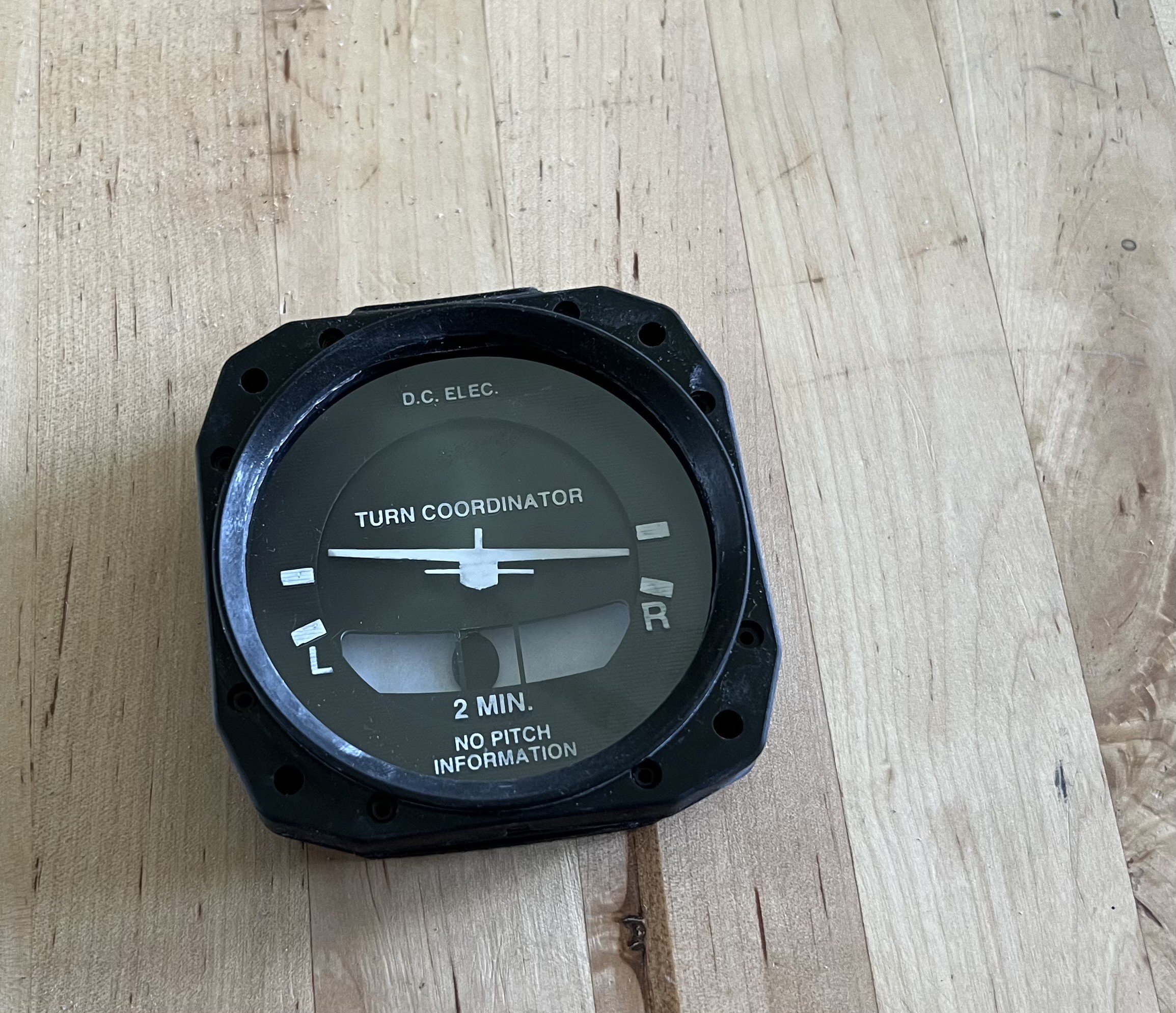
Although Captain Bob's design was intended for FDM printers, I had no trouble adapting it for my resin printer. Additionally, since I don't own a laser cutter, the clear screen is not a laser-cut piece of acrylic glass as originally designed, but rather a simple overhead transparency sheet cut with my trusty eight-year-old Silhouette Portrait cutter. It looks surprisingly convincing and also serves as dust protection for the instrument.
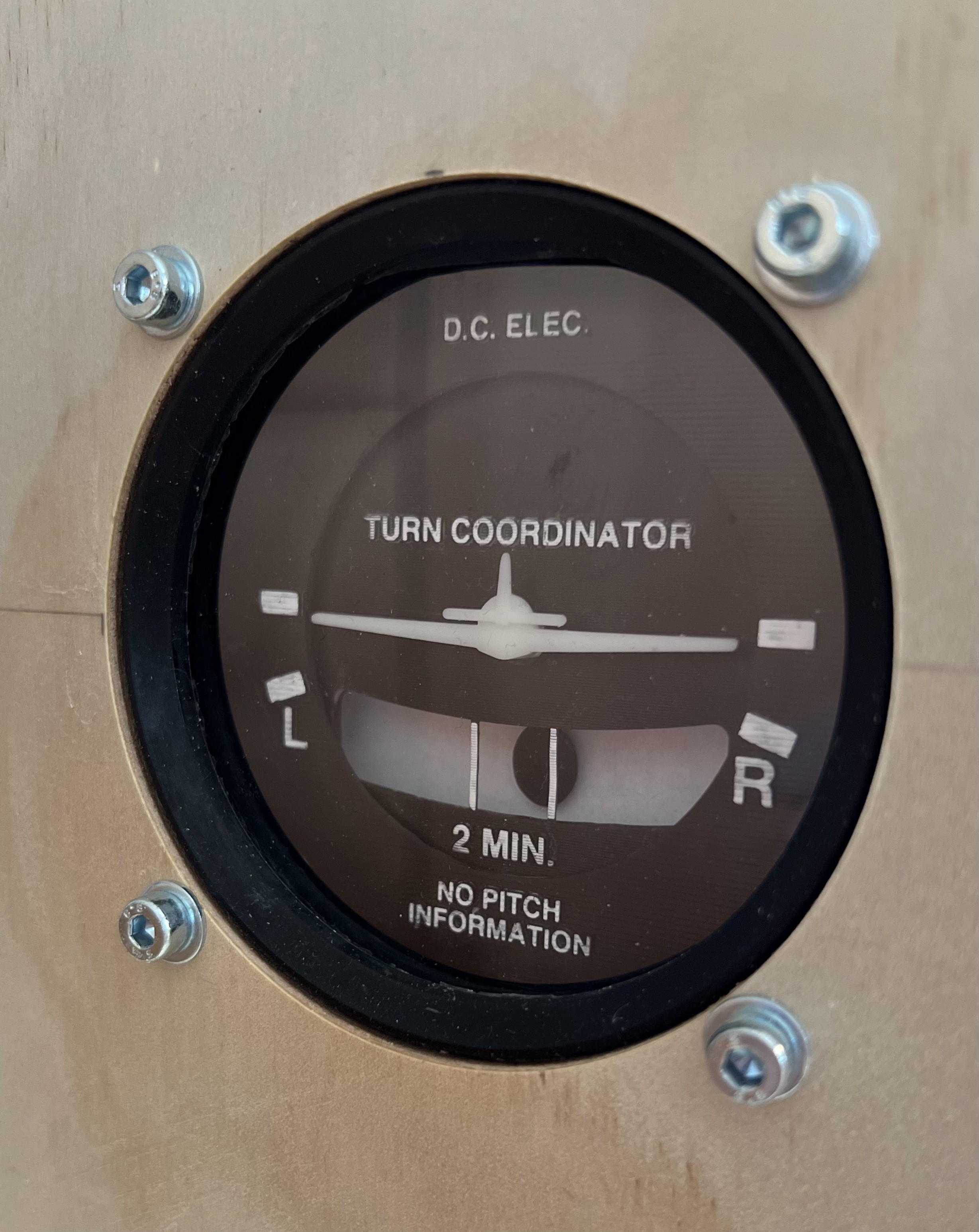
After a first dry fit, I decided to redesign the little airplane needle, as Captain Bob’s version is tailored for a Cessna 172, whereas I am building a dashboard for a Piper Arrow III. Using close-up screenshots from my flight simulator as a reference, I designed this alternative instrument needle in Fusion:
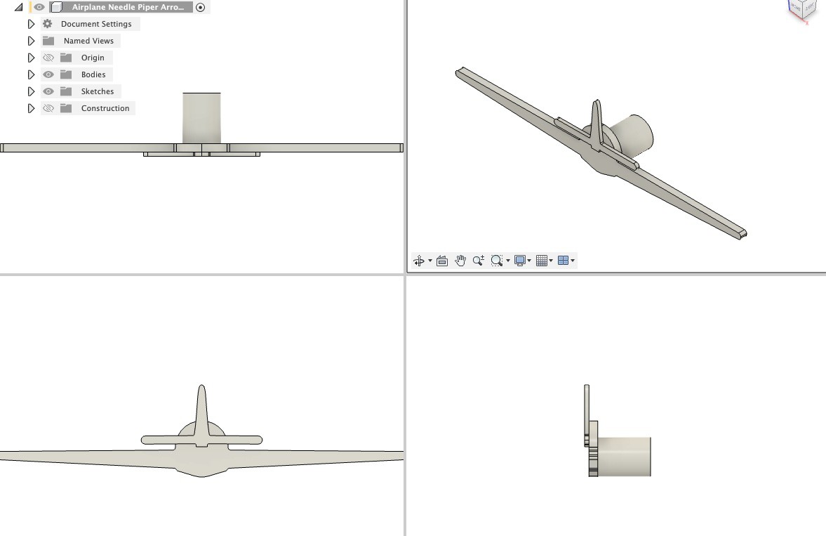
If someone is interested, here's the Fusion file: https://bitbucket.org/zaggo/pa-28-dashboard
And here's the final design:
#include <SwitecX25.h>
#include <si_message_port.hpp>

// standard X25.168 range 315 degrees at 1/3 degree steps
#define STEPS (315*3)

SiMessagePort* messagePort;

// For motors connected to digital pins 4,5,6,7
SwitecX25 motor1(STEPS,4,5,6,7);
SwitecX25 motor2(STEPS,8,9,10,11);

static void new_message_callback(uint16_t message_id, struct SiMessagePortPayload* payload) {
  if (payload == NULL) { return; }
  if (payload->type != SI_MESSAGE_PORT_DATA_TYPE_FLOAT) { return; }
  float relPos = payload->data_float[0];
  messagePort->DebugMessage(SI_MESSAGE_PORT_LOG_LEVEL_INFO, (String)"Received position: "+relPos+" for motor: "+message_id);
  switch(message_id) {
    case 1:
      motor1.setPosition(relPos * STEPS);
      break;
    case 2:
      motor2.setPosition(relPos * STEPS);
      break;
  }
}

void setup(void)
{
  // Init library on channel A and Arduino type MEGA 2560
  messagePort = new SiMessagePort(SI_MESSAGE_PORT_DEVICE_ARDUINO_MEGA_2560, SI_MESSAGE_PORT_CHANNEL_P, new_message_callback);

  // run the motor against the stops
  motor1.zero();
  motor2.zero();

  // start moving towards the center of the range
  motor1.setPosition(0);
  motor2.setPosition(0);

  messagePort->DebugMessage(SI_MESSAGE_PORT_LOG_LEVEL_INFO, (String)"Servos zeroed and driver ready");
}

void loop(void)
{
  messagePort->Tick();
  // the motor only moves when you call update
  motor1.update();
  motor2.update();
}
And here's the companion LUA script in AirManager:function new_message(id, payload)
-- Do something with the message from the Arduino
end
servo_driver = hw_message_port_add("ARDUINO_MEGA2560_P", new_message)
function turnrate_callback(deg)
-- value between 0.0 ... 1.0, 0.5 = 0° 0.2=-90° 0.78=+90°
local clippedDeg = var_cap(var_round(deg,3), -110, 110)
local v = 0.5 + (clippedDeg/90) * 0.29
-- print("Turnrate: "..deg.." clipped: "..clippedDeg.." v = "..v)
hw_message_port_send(servo_driver, 1, "FLOAT", v)
end
xpl_dataref_subscribe("sim/cockpit2/gauges/indicators/turn_rate_roll_deg_pilot", "FLOAT", turnrate_callback)
function sideslip_callback(deg)
-- value between 0.0 ... 0.156 0° = 0.082
local zeroPos = 0.087
local clippedDeg = var_cap(var_round(deg,3), -90, 90)
local v = zeroPos + (clippedDeg/90) * (0.156-zeroPos)
local clippedV = var_cap(v, 0, 0.156)
-- print("Sliprate: "..deg.." clipped: "..clippedDeg.." v = "..v.." clippedV = "..clippedV)
hw_message_port_send(servo_driver, 2, "FLOAT", clippedV)
end
xpl_dataref_subscribe("sim/cockpit2/gauges/indicators/sideslip_degrees", "FLOAT", sideslip_callback)


Comments
Post a Comment