Apologies for not posting in six months—I didn’t expect summer to bring so many distractions!
Here’s a quick summary of what happened during the hiatus:
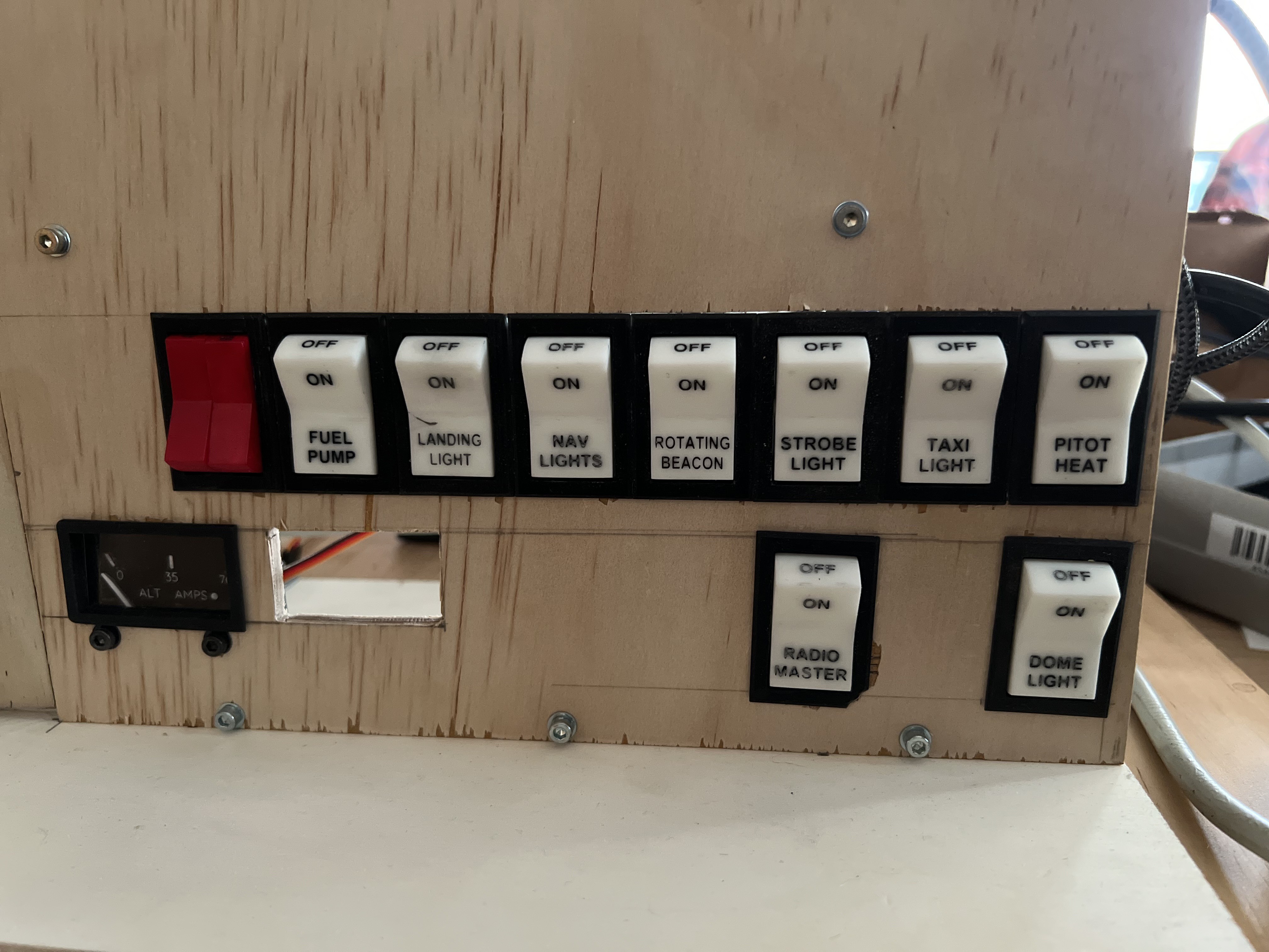
Switches
Still in spring, I designed, printed, and installed all the switches for the main switch panel.
The switches are based on the elegant design by Jay727 on Thingiverse. Using this design as a foundation, I created a “full-width” version of the switch and embossed the writing on both the front and top of the buttons.
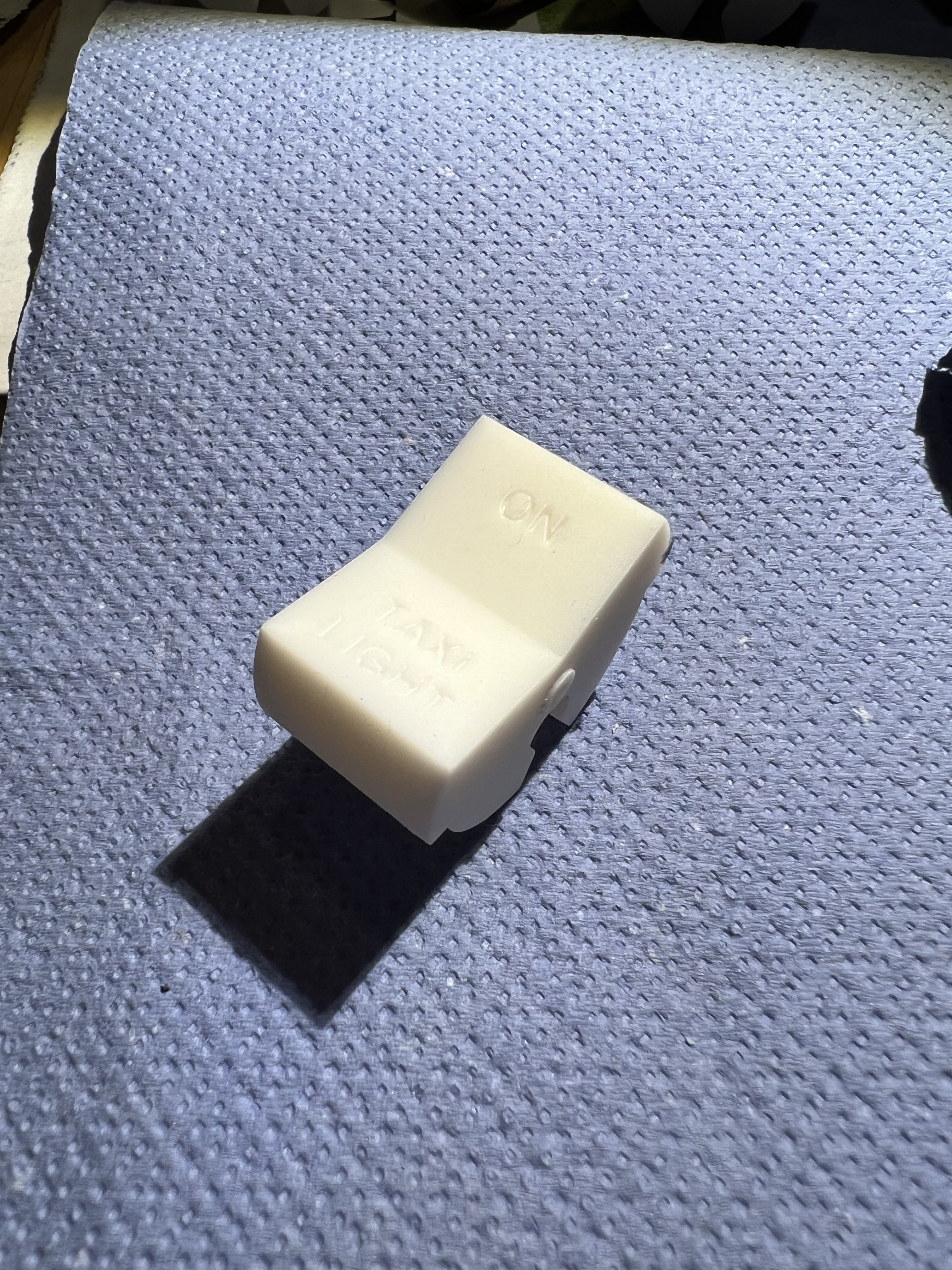
I printed the switches in white “ABS-like” resin:
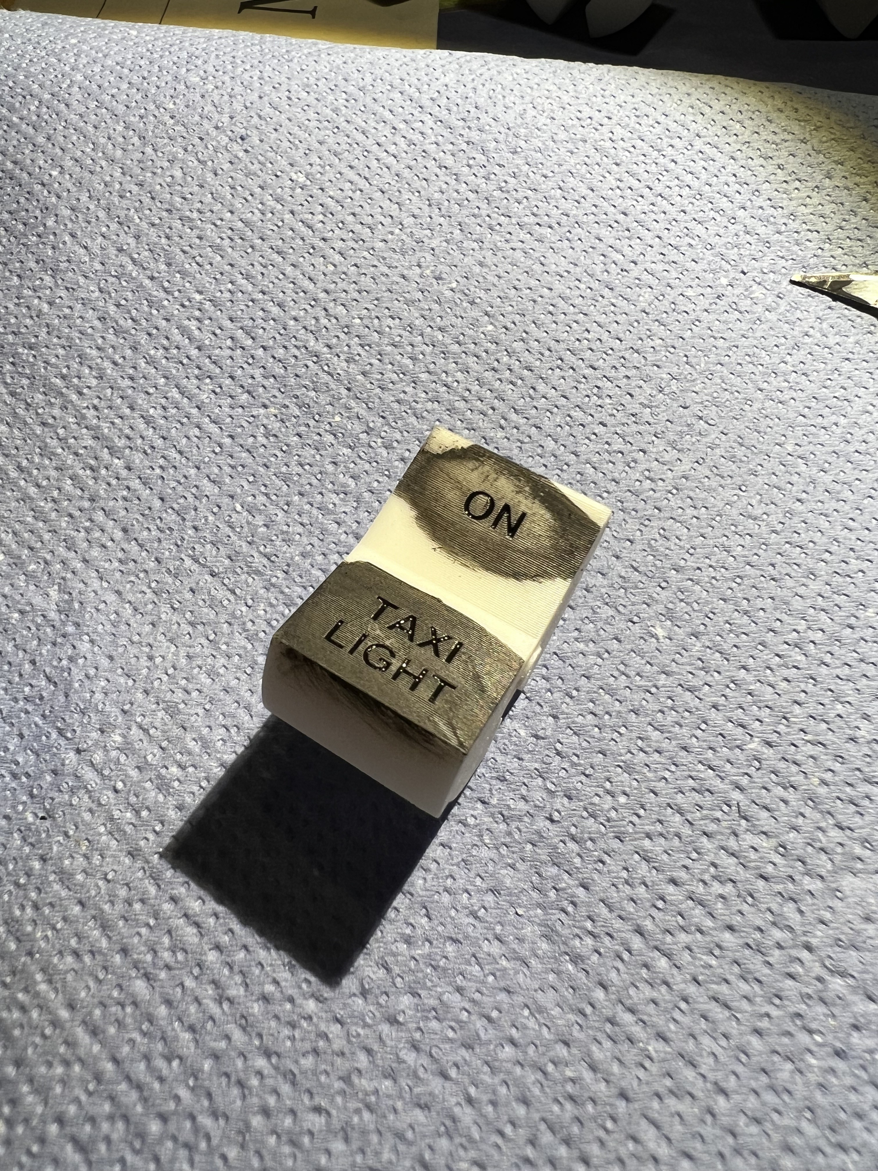
Next, I applied thinned black paint to the areas with writing, ensuring that the paint filled all the grooves of the letters.
Once the paint dried, I sanded away the excess paint and any faint layer lines from the print. Using wet sandpaper was crucial to minimize the (likely unhealthy) microplastic dust.
Here’s a short video showing the post-processing of one of the painted switches:
Unfortunately, I didn’t have any red resin for the power switches, and I didn’t want to buy an entire bottle of resin just to print two small parts. So, I printed them in white resin and painted them red with some nail polish I borrowed (stole) from my wife.
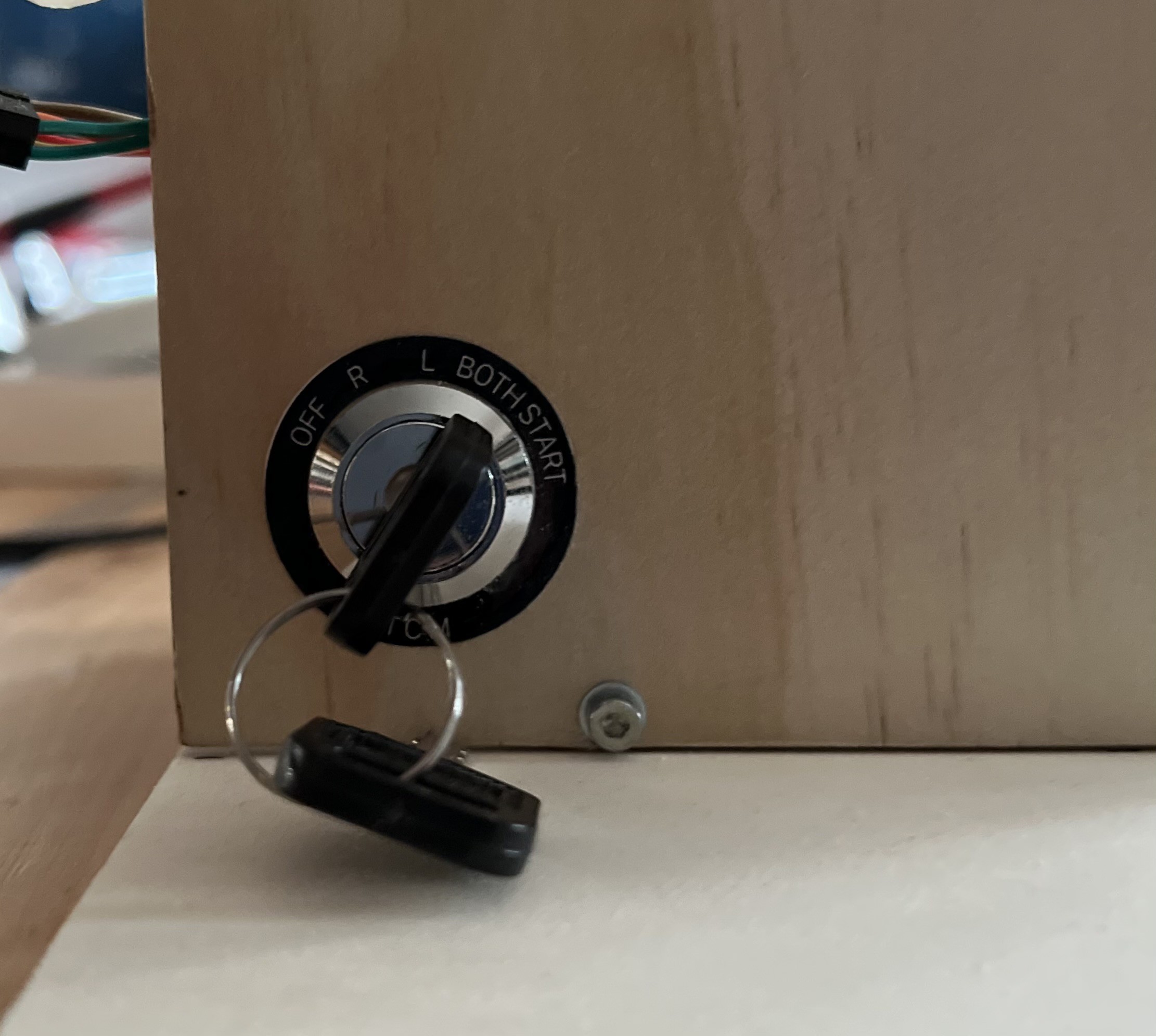
I only made small changes due to a slightly different lock mechanism and the fact, that I printed parts from it in resin. If you want to know more about this design, please check out Captain Bob's Youtube video.
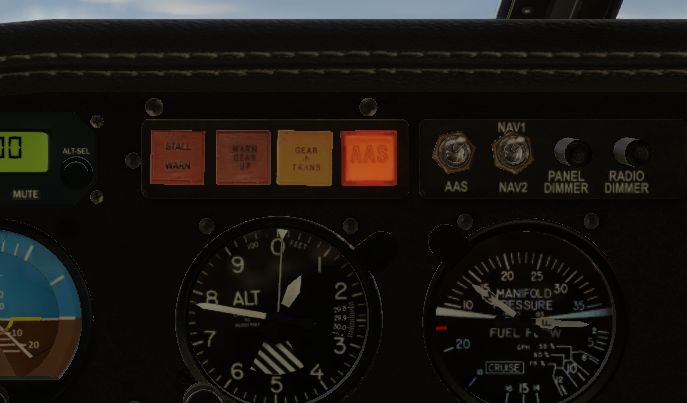
Annunciator lights
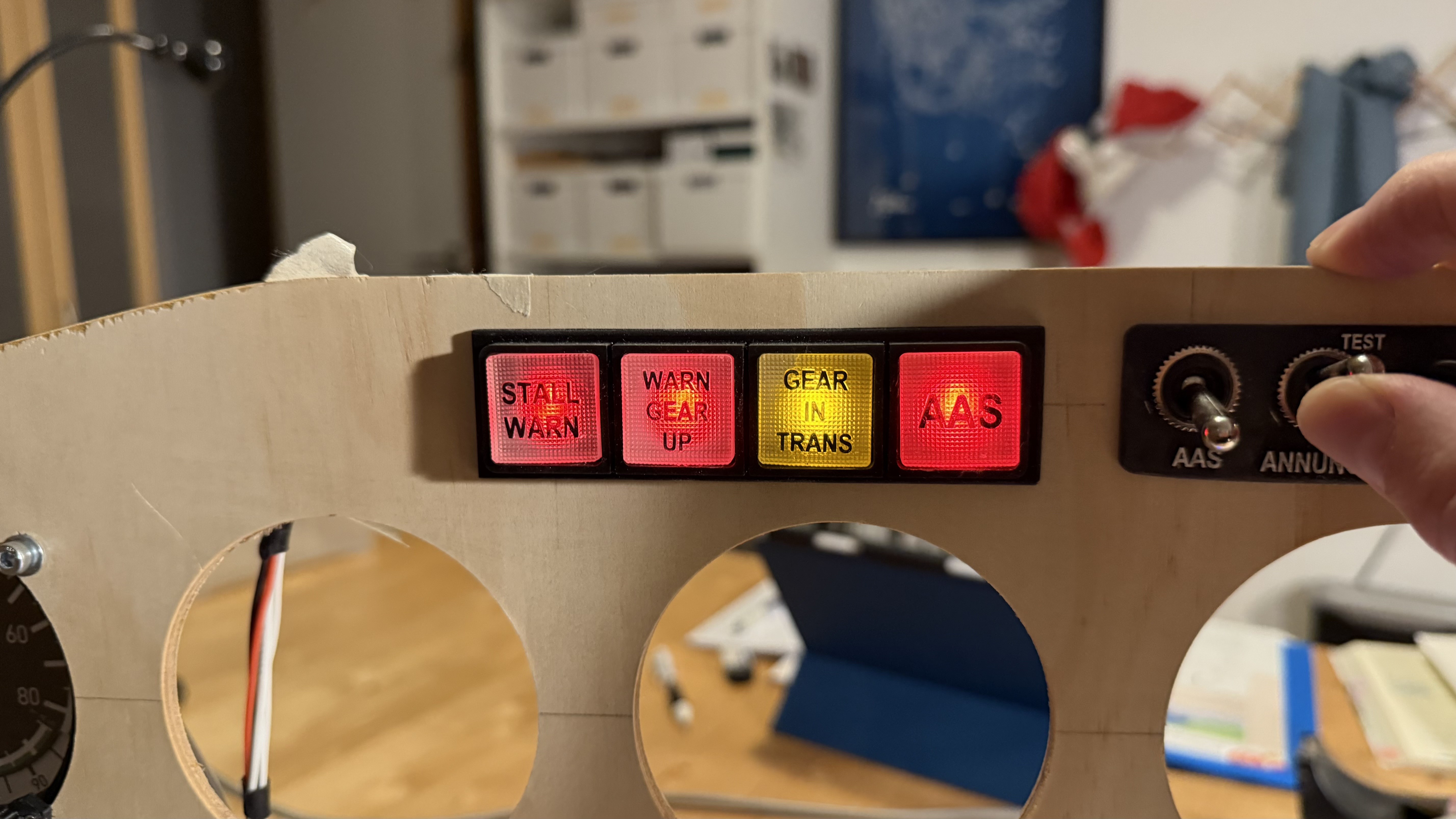
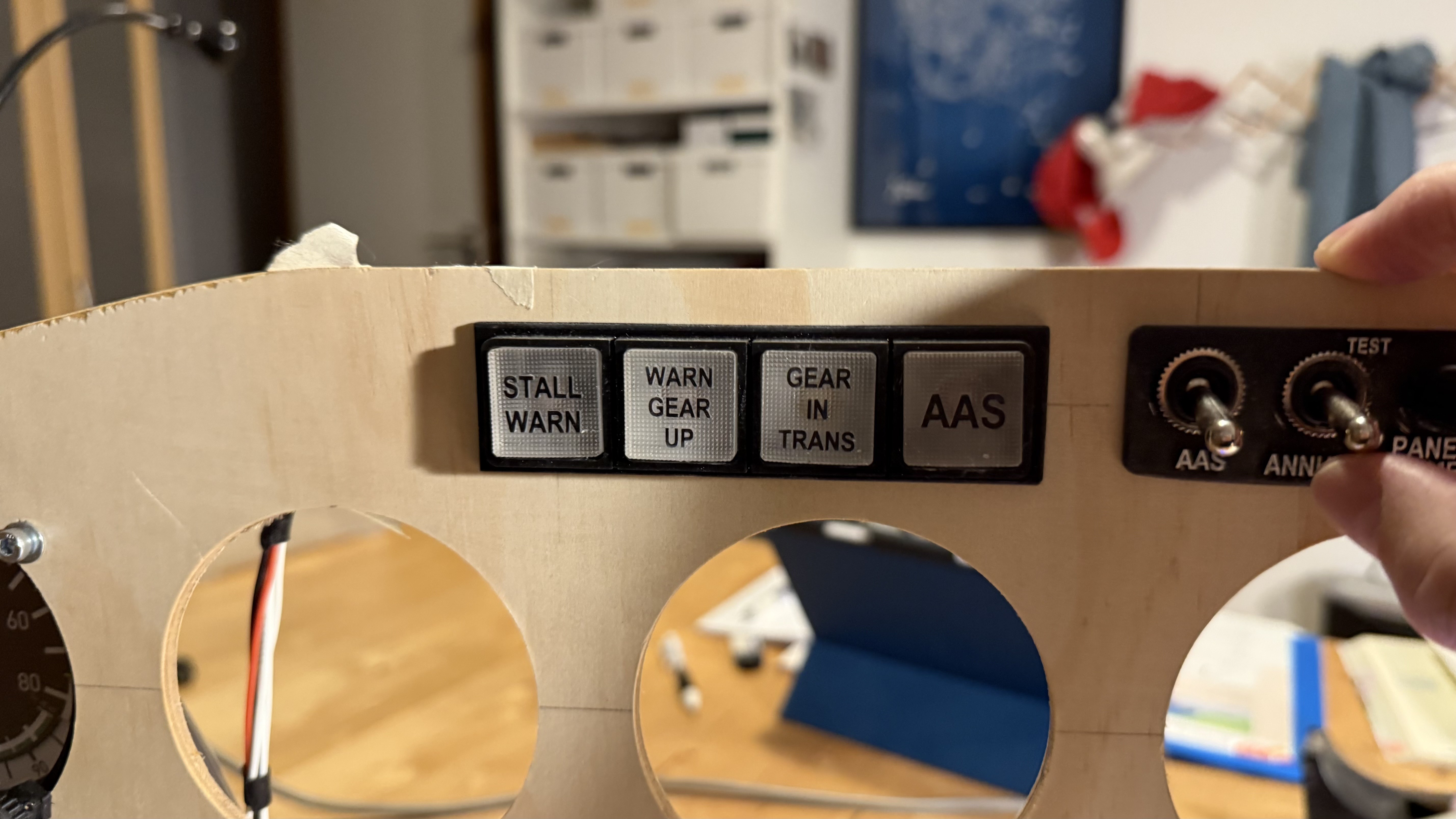
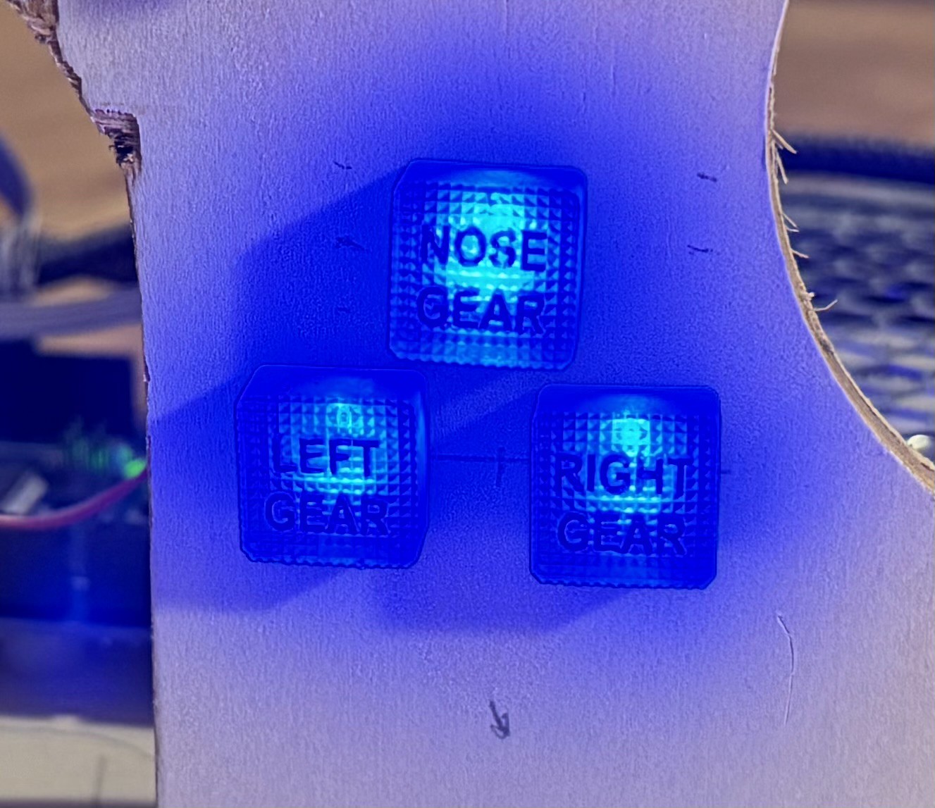
Next, I printed several annunciator lights. Normally, these lights are made from colored transparent plastic with white lights behind them:
Since I only have uncolored clear resin, I decided to print them in clear plastic and use colored LEDs behind them. This way, they still display the correct color when lit, which works perfectly fine for my needs.
I designed four large lights for the annunciator panel and four smaller ones for the gear and motor starter indicators.
(though they’re hard to photograph…)
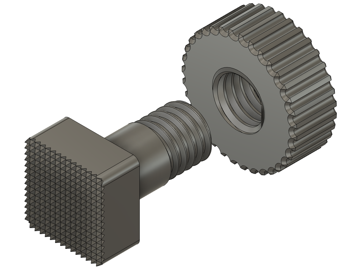
The lights are designed for easy installation: they feature a threaded back end and a matching printed M8 nut to hold them securely in place. If text is required, it is directly integrated into the design as embossed lettering, which I later colored with a black marker.
The LEDs are simply press-fitted into a hole at the back.
Long story
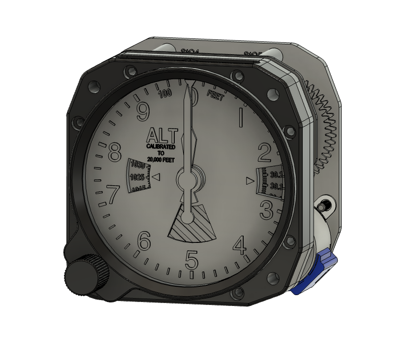
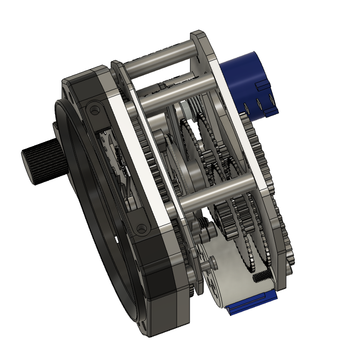
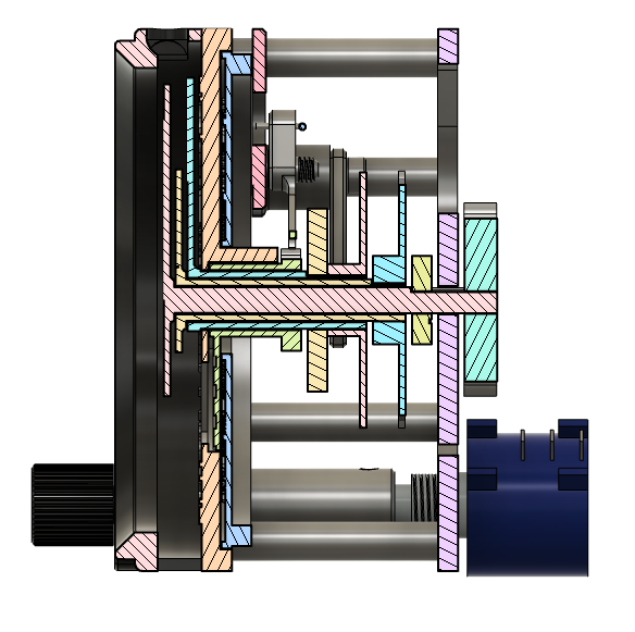
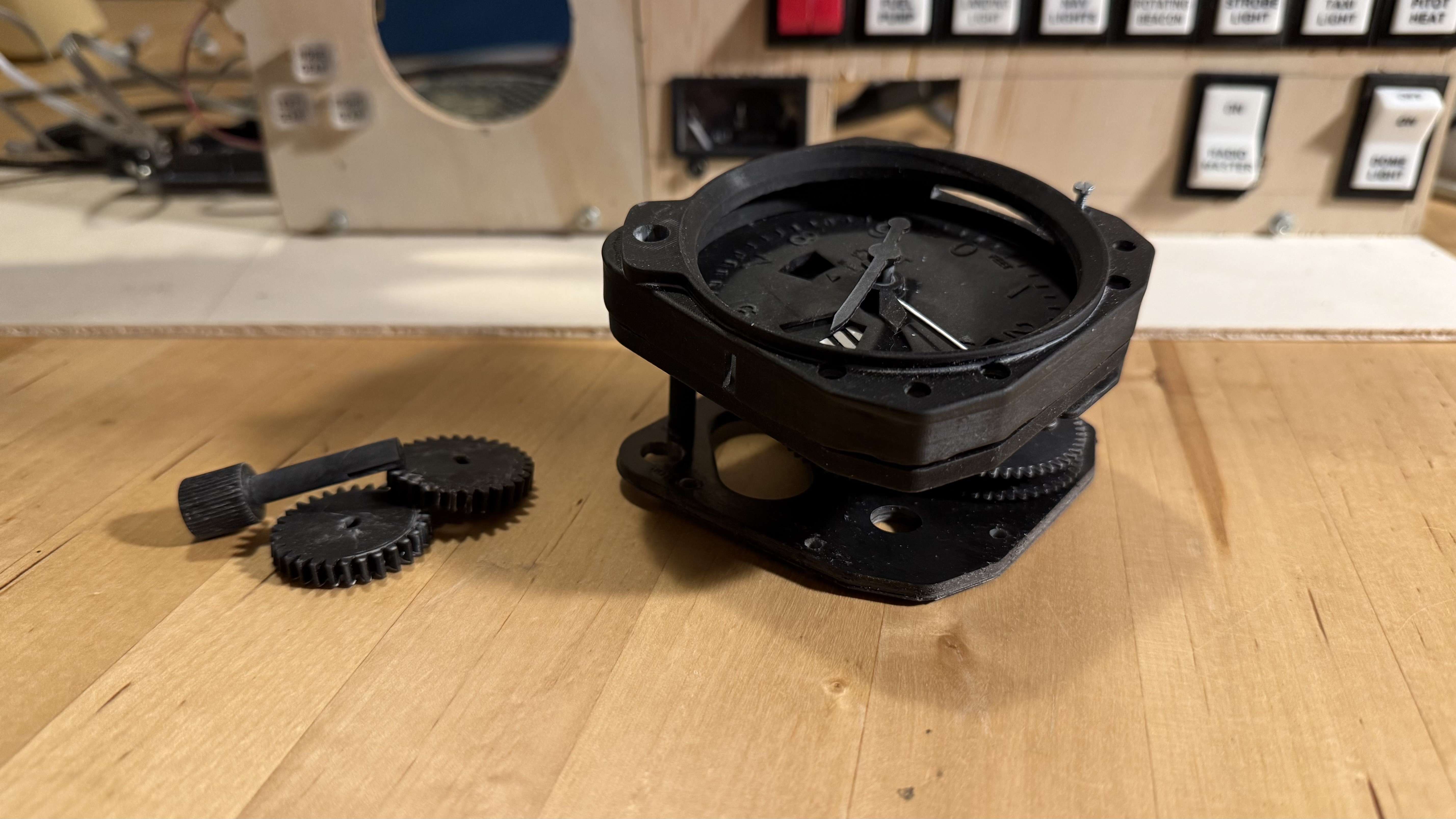
And then there’s the altimeter…
I initially checked out Captain Bob’s altimeter design, but I didn’t like the mechanics, and it didn’t match the altimeter in my PA28 simulator. So, I decided to redesign it.
That’s when I had the bright idea to replicate the mechanics of the real thing. Instead of using three separate steppers for the three needles, I began designing a clockwork mechanism driven by just one stepper. Then came the 10k-flag… and then… and then…
Long story short: after three complete design cycles, numerous test prints, and one full prototype, it doesn’t work…
… yet!
There are several flaws in the design—nothing unfixable, but still enough to require a lot of additional work.
Maybe it wasn’t the summer that kept me away from this project after all? Who knows?
Hi, After starting a build log for this project on another platform a few years ago, I ran into issues with how the blog was organized there. So I decided to move my build log for my DIY flight sim cockpit here. I’m hoping this move will make it easier to post updates more regularly and keep track of the project’s progress. I’ll be moving my existing posts over from the old build log and then share an update on where the project currently stands, along with the next steps. So, here’s what’s happened so far… The Beginning (January 2024) Piper Arrow III Sim Cockpit Originally, I set out to build a dashboard for a Piper Arrow III for use with flight simulators. The idea was to keep it modular so it could be set up and taken down easily on a desk, since I didn’t have space in my apartment for a full, stationary cockpit. The setup was meant to be centered around my CH Products yoke and rudder pedals, which I had already owned for years. Since then, the scope of the project has evolved quite...
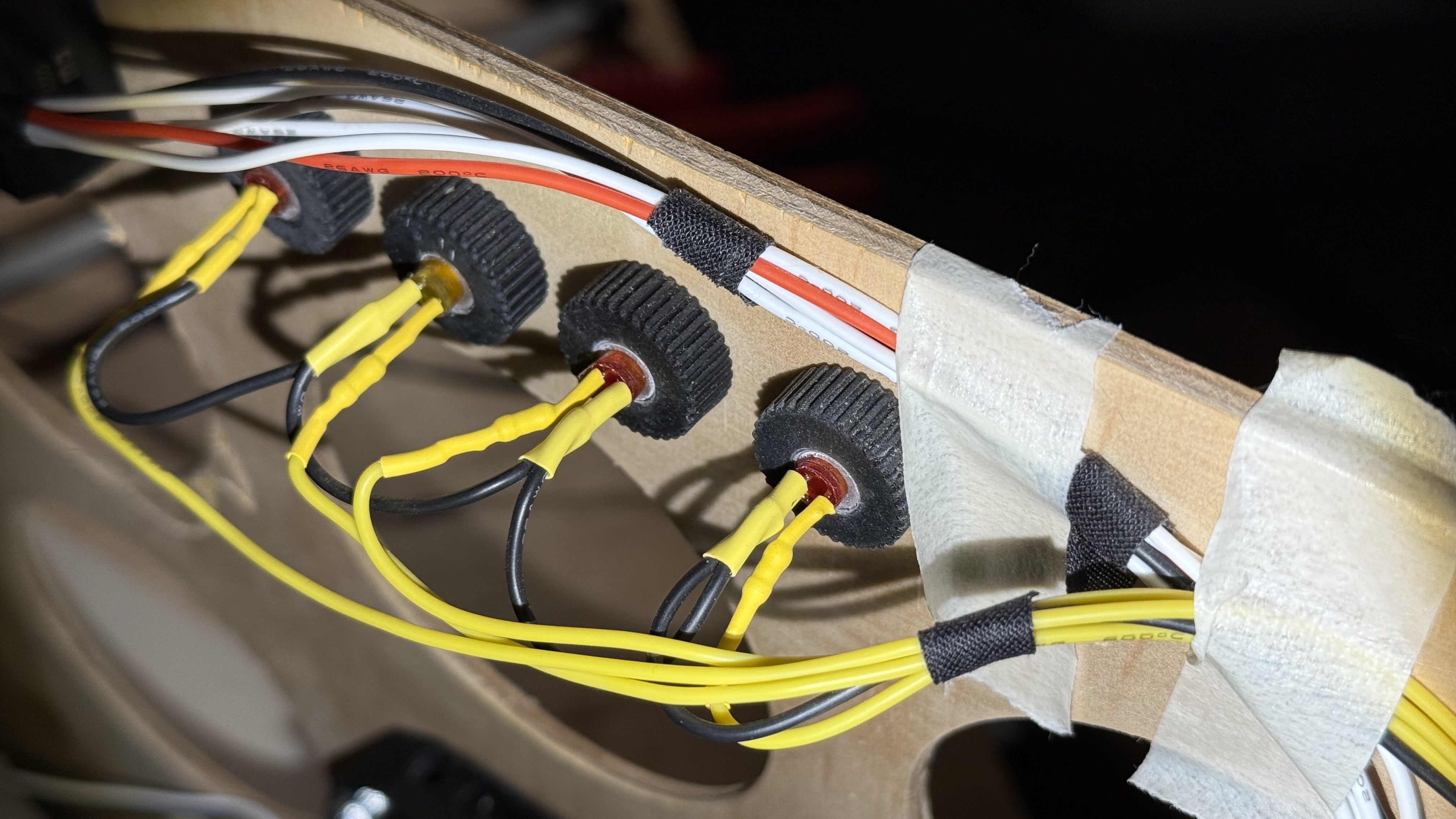
When it comes to the cockpit build, four main things happened (roughly speaking): I finished several additional instruments for the dashboard Changed the core software architecture Brought the Stewart platform up from the basement and reworked it both mechanically and electrically Started building a full cockpit on top of the motion platform Even though this list is roughly in chronological order, I’ll start with point 2, since it ended up influencing point 1 as well (at least towards the end). Integration Hell (aka Cable Chaos) Changing the core software architecture Even though it’s really convenient and quick to hook everything up using 3rd-party solutions like Air Manager or MobiFlight, things get messy fast once the project grows beyond a certain size. It’s not just that discrete wiring for stepper motors, encoders, buttons, and so on quickly turns into an impenetrable mess of cables. What really stood out to me is how a slightly more complex setup can turn into a maint...
Originally published 1. May 2024 The first device I built was the GNS 430 GPS unit. Here's the finished thing: I wanted this to have with backlit buttons and real dual rotary encoders. After searching the web for a while it became clear, that I had to design this myself. The screen content comes directly from the flight sim. But since I'm currently running the sim on a Macbook Pro, and thus do not have an option to connect too many external displays, I use AirManager for grabbing the GPS' display content directly from XPlane and sending it via a network connection to a Raspberry Pi 4. This works surprisingly well, even over wifi. Unfortunately the Raspberry doesn't have enough GPIO pins to also drive all the buttons and encoders. I originally planned to build two GNS 430 units anyway (as there are two of them in the simulator) and it's no problem for the Raspberry Pi 4 with its 2 HDMI connectors (and the AirManager/AirPlayer combo) to provide the display content for...


Comments
Post a Comment